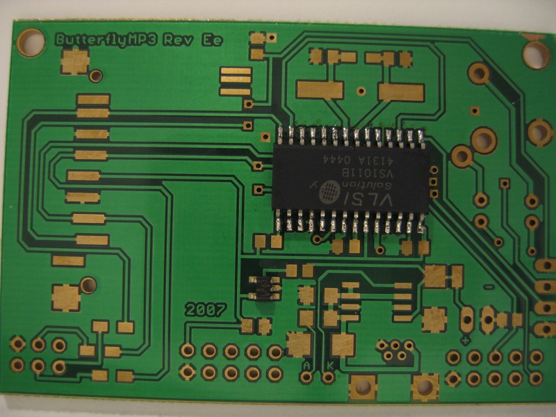
OverviewThe following pages cover the step by step instructions on how to solder the Rev F PCB. (NOTE: The PCBs in the example pictures and videos are a prototype
version of the PCB and were mistakenly labelled Rev Ee)
Click the images to zoom in. All the construction example videos from these pages are also available on YouTube. Some good intro to soldering videos can be found at curiousinventor.com and also at sparkfun on YouTube (some of the videos may be upside down on this website).
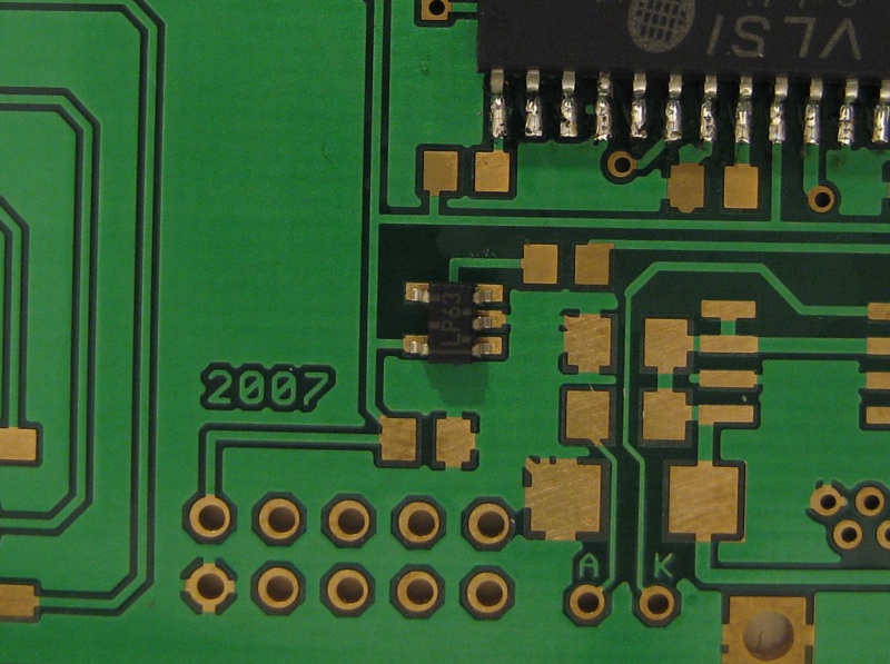
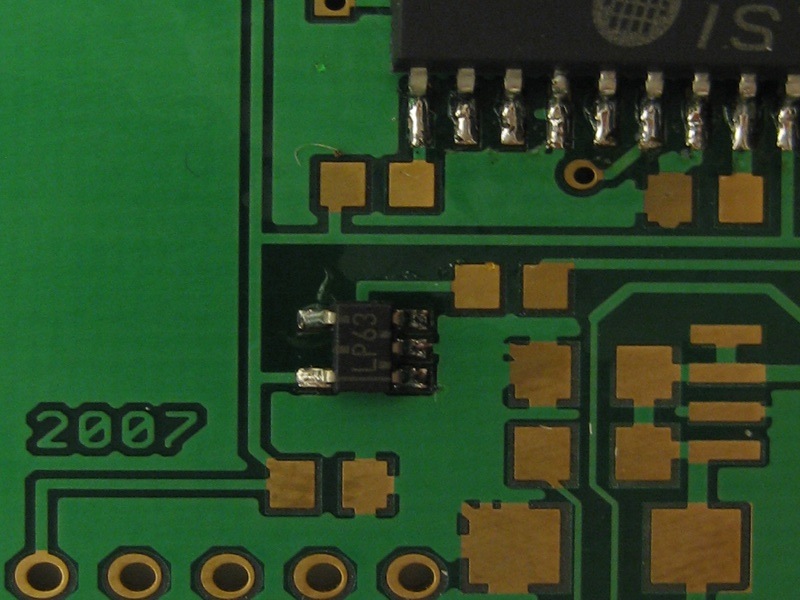
2 - U4 LP2981 2.8V low Dropout regulator
This component is probably the hardest in the project due to its fine pitch small package size. I usually solder this device second having warmed up and settled my shaky hands on the VS1001. I again use my standard approach of 'paint and slide' the first pin to get the position right and then finish the other pins. This device has such small pads that you may find no additional solder is required (other than the small amount carried on the tip). If the pins bridge then simply try whipping the solder away with a dry (clean) tip or use some de-soldering braid. For the large SOIC-28 package used in the previous step I simply used my antistatic finger to slide the chip into place. With a small package such as this you will probably want to use tweezers. I would recommend stainless-steel for being non-magnetic, antistatic and resistant to heat. As for the style of tweezers I would go with what ever you find most comfortable. Some people like curved-pointed tips while others like simple flat angled tips. The following is my attempt to demonstrate how to solder this chip The LP2981 is a low dropout voltage regulator from national semiconductor. The version we use here regulates the battery voltage to 2.8 voltes and has 200mV dropout. This means that it should operate normally until the input voltage drops to 3.0 Volts. We need this component as the MMC/SD card is only rated to 3.6V a fully charged lithium cell charges to 4.2 Volts. This device was chosen to give us maximum operating range within the standard operating levels of the lithium battery (3.6 +/- 0.6V) A previous design used a switched capacitor regulator. While this appeared to be more efficient on paper, in practice it resulted in much higher current drains when the battery was low that in turn caused the battery to drain much faster. While this device regulates the voltage the system (including the AVR Butterfly board) low power modes and automatic shutdown on low battery is handed by the AVR which monitors the current battery voltage via an analogue input. The correct charging of the lithium polymer is handled by the next component....
|