To celebrate getting the GPIO working using WiringPi from Gordon Henderson I thought I’d have a quick look at the difference between running some code on an Arduino compared to running almost the same code on a Raspberry Pi (RasPi).
It is worth noting now that the setups I’ve been using to test with are all powered from a separate 3.3V supply with the grounds linked. Nothing is being powered via the RasPi itself to avoid drawing too much current should I make a mistake. When working with the RasPi you should be careful as the RasPi will not take kindly to static discharge, connecting things backwards or the wrong voltage levels.
The really great thing about Gordon’s library is that by using it I am able to transfer Arduino code to the RasPi with only a few simple changes. Obviously not everything in the Arduino libraries are present, but the basic I/O manipulation is plenty for some simple applications.
MAX6675 thermocouple interface example
The MAX6675 from Maxim is an SPI Bus based thermocouple convertor that I built a breakout board for a while back. You can find out more information about that project in this earlier post.
As a simple test I took the basic example from the MAX6675 thermocouple interface library and adapted it to run with the WiringPi library on the RasPi.
I initially ported the example and library to C as the WiringPi was in C and I had a couple of issues compiling mixed C and C++ properly. After a bit of investigation I found that when explicitly including the libraries as C the compiling problems go away. Below is an example of how to modify the wiringPi.h file to ensure it is included as C and not C++. Gordon has said he will make this change to the library on the next release. Once I had sorted out the makefile to use g++ rather than gcc I was able to compile and link successfully.
Listing 1: Explicitly declaring a header file as C
 #ifdef __cplusplus
 extern "C" {
 #endif

 // wiringPi.h Code goes Here
 //  or
 // #include <wiringPi.h>

 #ifdef __cplusplus
 }
 #endif
While compiling and linking of the example was now okay, the next problem was that when run, the program just exited with a “Segmentation Fault” (segfault). I didn’t even see the error message when running as root with sudo, it was only when running as the standard user (pi) that it became apparent that something was wrong with the software rather than the hardware.
When I had run previous examples as the standard user I would see a permissions related error complaining that the program could not access the “/dev/mem/” device. This error comes from the part of the WiringPi library that sets up memory access to the hardware registers in the Broadcom BCM2835. This clue told me that the wiringPiSetup routine was not being run. This in turn showed me that the global object representing the temperature sensor was being constructed before the WiringPi library was being setup.
The solution to this particular problem was simple enough. I edited the MAX6675 library so that it calls wiringPiSetup directly when initialising. I also set an internal flag if this succeeds. In addition to this I modified the methods to exit with an error if the flag has not been set. This means that none of the MAX6675 library methods should ever call WiringPi functions without the appropriate initialisation having taken place and succeeded beforehand. My code for this example is here. A more general solution might be to add this flag to the WiringPi library itself.
LED Display (MLMC) and Temperature Combined Example
Following my success with the temperature sensor I decided to push the boat out a little further and try to interface to my MLMC LED display system.
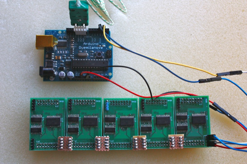
The MLMC LED display is a set of LED dot matrix control PCBs I designed to use up some unusual LED modules I had lying about. You can get the full story in this blog post or on the website.
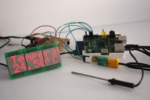
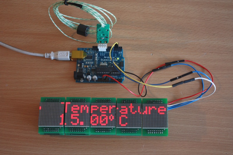
This was a simple demonstration with the RasPi reading from the thermocouple interface and then displaying the temperature on the display. For this example I wrote everything in C. The MLMC interface is very simple and involves clocking 16 bit words of data using two pins, one for data and one for clock. Each word represents a single column on the LED display. This low speed (~5Kbps) synchronous protocol was originally implemented by directly manipulating the digital I/O pins on the Arduino and so was very simple to port to the RasPi with the WiringPi library.
While the ported program functions very well, the waveforms obtained from the RasPi are quite different to those achieved with the Arduino. This is a good example of how the same simple code can be quite different when ported between platforms.
MLMC Clock Waveforms
The function used to send serial data to the MLMC is shown below. This code has a 75µs delay between switching the level of the clock and this gave uniform pulses on both systems. The pulses also appeared consistent from one run to another.
Listing 2: MLMC serial data sending routine
const int spidelay_us =75;

void Send_byte( char data ///< 8 bit data to be sent
			   ) {
    uint8_t temp;	// local copy of the data to be shifted out
    uint8_t i;

    temp = data;
    for (i=0; i<8; i++) {
		// start the cycle with the clock pin low
        digitalWrite(clockPin, LOW);

		// clock out a single byte
        if (temp & (1<<7)) {
            digitalWrite(dataPin, HIGH);
        } else {
            digitalWrite(dataPin, LOW);
        }

		// wait for data bit to be set up
		delayMicroseconds(spidelay_us);

		// clock the data out by producing a rising edge
        digitalWrite(clockPin,HIGH);

		// wait for mlmc to read the data bit in
        delayMicroseconds(spidelay_us);

        // shift data along by one
        temp <<= 1;
    }

	// leave both pins low when idle
    digitalWrite(clockPin, LOW);
    digitalWrite(dataPin, LOW);
}
The following scope traces are the result of executing Listing 2 on the Arduino:
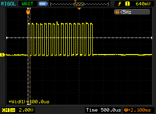
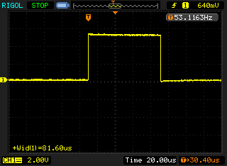
Arduino has a total pulse time of approximately 80µs for the first clock pulse to MLMC. This extra 5µs I assign to the time taken to call the digitalWrite function, a single shift operation and iterating the for-loop.
The next two traces in figure 3 and figure 4 are produced when running the same code on the RasPi:
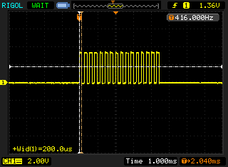
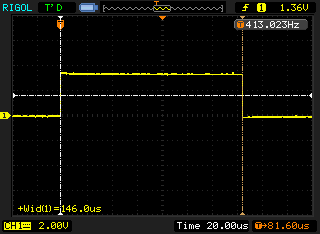
You can notice that while the pulses look identical at a quick glance the RasPi has 150µs pulse width; almost double that of the Arduino. I assume that the delayMicroseconds function, which only guarantees that a minimum of the given microseconds have elapsed before returning, is releasing control to the operating system and coming back a lot later than expected. As the delay implementation in the WiringPi library simply calls nanosleep I am surprised this operation takes twice as long. There may be a number of causes for this behaviour:
- There might be a bug in the way the delay function is implemented.
- The shift and for-loop iteration might have compiled in a very inefficient way.
- The operating system simply cannot schedule other tasks quickly enough to return from
nanosleepand meet our expectations.
MAX6675 thermocouple interface
This loop was clocking data in from the MAX6675 chip via a “bit-banged” interface. The main loop did not have a delay and was toggling bits as quickly as possible while shifting in the value via a single GPIO pin.
Listing 3: SPI send section from the MAX6675 library
digitalWrite(_CS_pin,LOW); // Enable device

/* Cycle the clock for dummy bit 15 */
digitalWrite(_SCK_pin,HIGH);
digitalWrite(_SCK_pin,LOW);

/* Read bits 14-3 from MAX6675 for the Temp
 Loop for each bit reading the value and
 storing the final value in 'temp'
 */
for (int bit=11; bit>=0; bit--){
	digitalWrite(_SCK_pin,HIGH);  // Set Clock to HIGH
	value += digitalRead(_SO_pin) << bit;  // Read data and add it to our variable
	digitalWrite(_SCK_pin,LOW);  // Set Clock to LOW
}

/* Read the TC Input inp to check for TC Errors */
digitalWrite(_SCK_pin,HIGH); // Set Clock to HIGH
error_tc = digitalRead(_SO_pin); // Read data

digitalWrite(_SCK_pin,LOW);  // Set Clock to LOW
digitalWrite(_CS_pin, HIGH); // Disable Device
The following traces in figure 5 and figure 6 show the results on the Arduino.
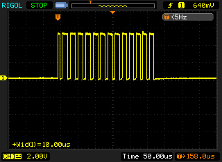
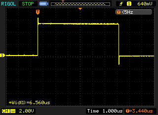
On the Arduino this code gave a uniform pulse train with the pulse widths measuring approximately 6-7µs. As the Arduino is running at 16Mhz I would like to think this could be optimised a lot more to get something like 120ns if I used some assembly or bypassed the Wiring/Arduino API, but that is an exercise for another blog post. 🙂
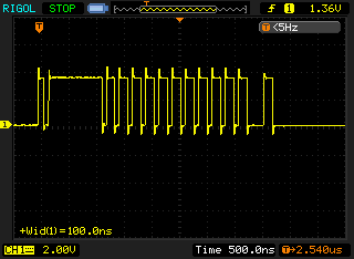
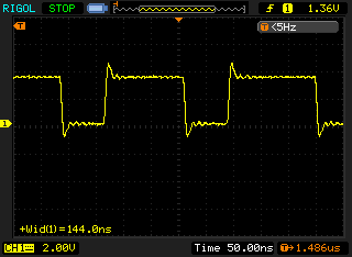
The RasPi on the other hand gave a very non-uniform pulse train. As this is synchronous communication, the clock does not need to be uniform, it dictates when the data line is read. The average pulse in this waveform is only 150ns wide which is approximately 48 times faster than the Arduino. Given that the RasPi clock speed of 700MHz is roughly 44 times faster then the Arduino clock speed of 16MHz, this makes sense.
The RasPi would vary any individual pulse length by up to a factor of two (from observation) but did not seem to be effected by increasing the load (multiple ssh sessions and running an openssl speed test). The RasPi would also continue to run the MLMC scrolling display and reading the temperature sensor without issues while another process was also reading the temperature sensor at the same time (single_temp.cpp from first example above). Even while openssl was doing speed testing (cpu usage at 98-99%) the visible operation of the screen was not effected.
Investigating Further
The long delay and changing pulse widths could be investigated further with a couple of short programs.
I could investigate the long delay further by looking at repeating the test with the system under different loads and noting the effect on the width and consistency of the pulses. To vary the workload on the RasPi I could use a tool like stress.
We could also step through many values while keeping the system load constant. This would give us an idea if their was a minimum overhead experienced by the delay function or if their was some sort of error in the calibration.
I will leave these as an exercise for another day as plenty of work has already been done on this sort thing before, although not specifically on the RasPi.
Conclusions
This was a very quick look into porting code from Arduino to Raspberry Pi. I found that it was not so difficult to port some very simple applications, the majority of the code would simply run unchanged.
While the code may compile and run, the actual operation of the code will always need to be checked carefully for timing issues and other unexpected behaviour when switching hardware and using new library implementations.
As these systems were using synchronous serial communication the exact shape of the waveforms did not actually need to be uniform for the system to work.
On review of the MAX6675 data sheet the timings slighty exceed the stated maximum clock freq of 4.3Mhz. So If I was intending to use this further I would introduce a short delay into the MAX6675 clock routine to ensure it complies with the data sheet.
The MLMC module operates perfectly with the timings achieved but we are operating at half the throughput we expected due to the delay function not operating identically to the same function on the Arduino. While this didn’t cause a problem in this simple test it could easily have done so in a slightly more complicated system.


